Strix
A twin-boom pusher aircraft designed as Experimental Amateur-Built, for a newly licensed pilot rather than a rated glider pilot. Nothing in it is drawn by hand: change one number and the 3D model, the structure, the weight statement and the performance figures all regenerate together.
- Role
- Designer
- Status
- Active redesign
- Engine
- Rotax 912 pusher
- Open questions
- Three
What it is
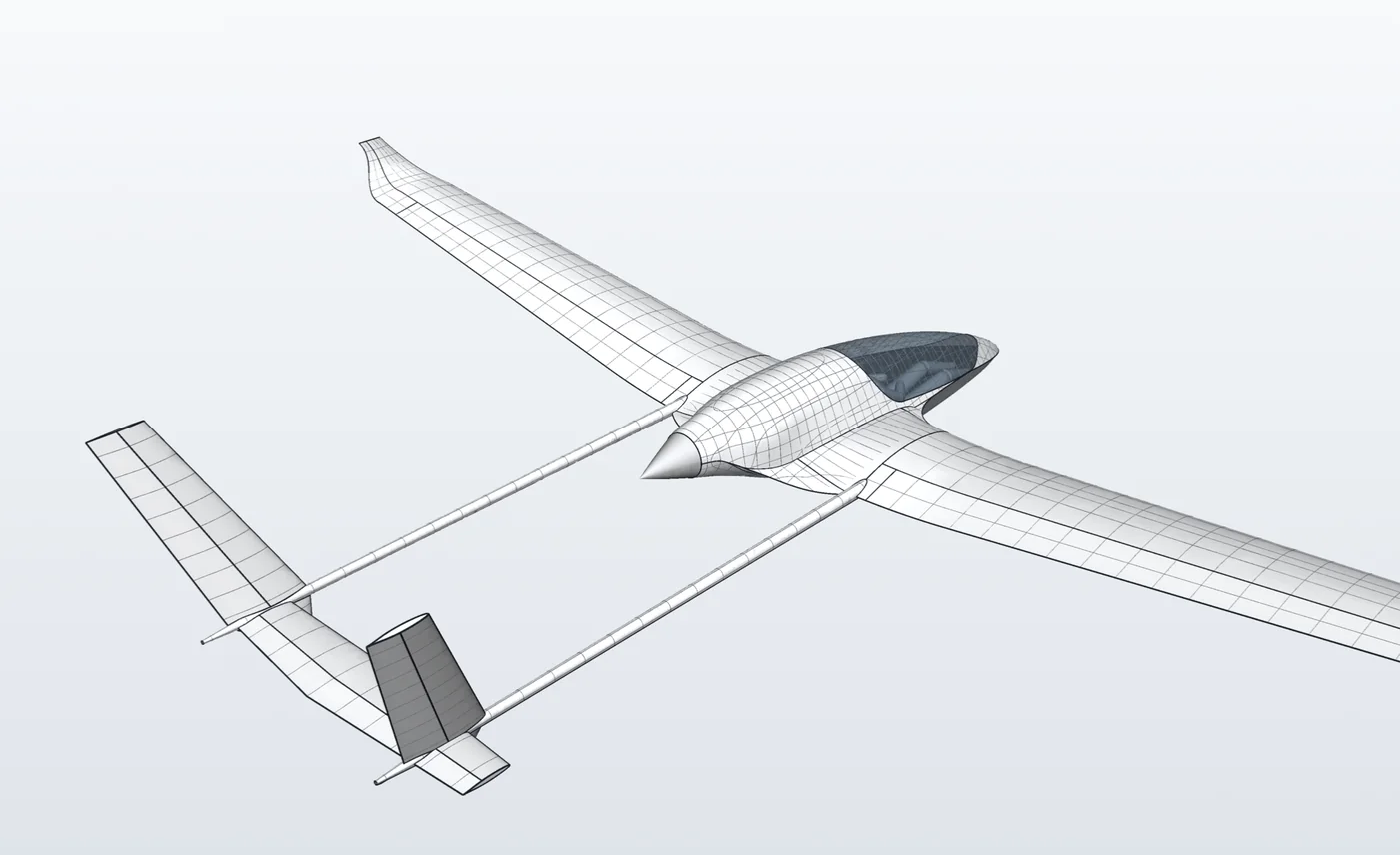
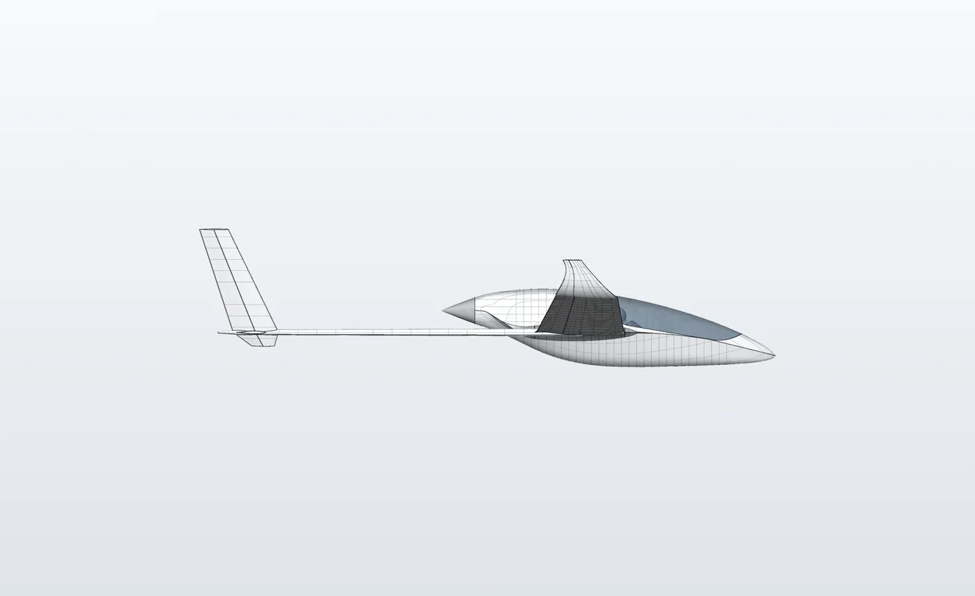
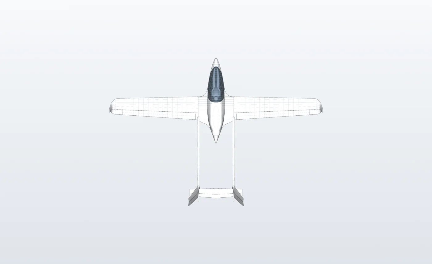
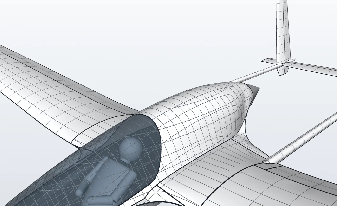
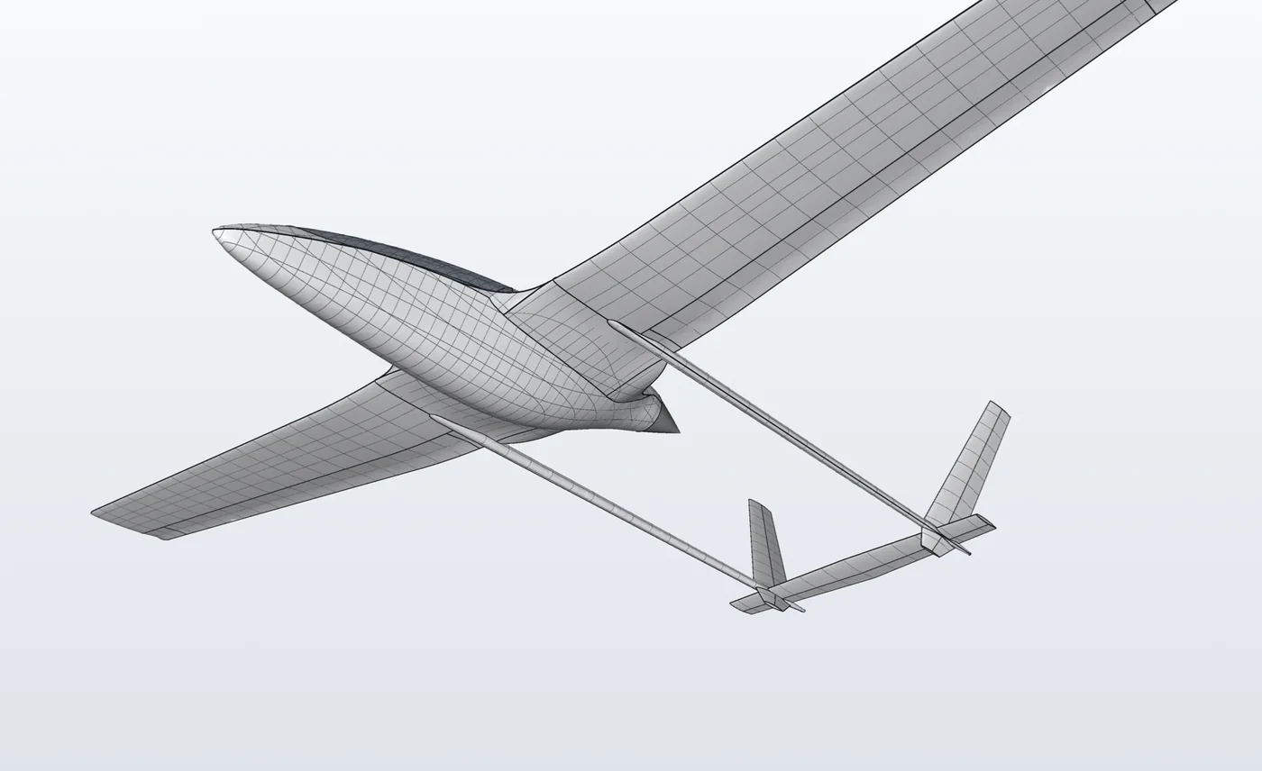
A four-stroke pusher mounted between twin booms, with the pilot and engine in a chined center-section pod, fixed tricycle gear, a ballistic airframe parachute, and a fixed-pitch propeller. The engine runs for the whole flight, so the glide ratio is a performance number rather than the mission.
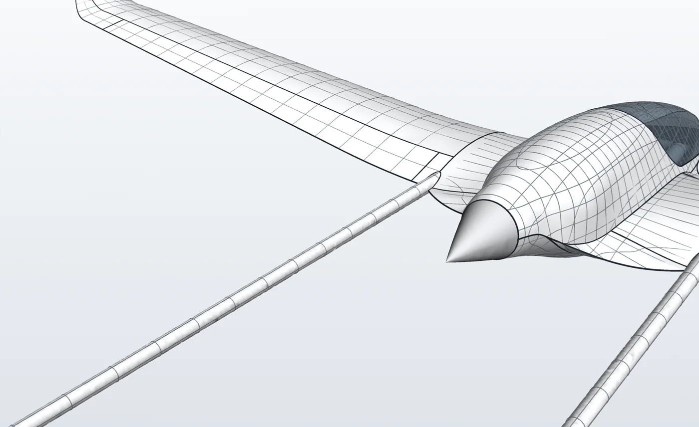
Looks are a stated requirement, not an afterthought: few edges, each one continuous and aligned with the planform, near-planar panels between them. There is a written surface-discipline reference the geometry is measured against.
I am not an aerospace engineer. What I am is someone who will not accept a number he cannot trace, which turns out to be most of the job.
This is the real geometry, exported from the parametric build and compressed for the web, not a hand-made web model. Keyboard: focus the viewer and use the arrow keys.
The current airframe
These are renders of the same model in the viewer above, the gated CAD surface shown plain. Whether a surface is actually fair is measured on the CAD itself, not judged from a render.
The decision worth explaining
The design has been reframed twice, and each reframe meant deciding which constraints were real and which had merely become habits.
It began under an ultralight category with a hard empty-weight limit, a stall ceiling and a fuel cap. Released from that, it became a self-launching sailplane: soar with the engine off, retractable monowheel, folding propeller. Then it was reframed again for the pilot who will actually fly it: engine on throughout, fixed gear, a parachute, a simpler propeller.
The wing did not grow when the stall limit lifted. Only the regulation had ever wanted it bigger.
A constraint you carry past its expiry gets quietly rewritten as a preference. Separating those two, in a design where every number leans on every other number, is the recurring work.
What was open, and how it closed
An earlier version of this page listed three unresolved questions. As of September 2026 all three are decided, each by a study rather than a guess:
- Span. The CAD used an 11.0 metre wing while the analysis used 14.2 metres. I ran fourteen candidate wings through the same weight, performance and stability chain. Wing area turned out to set the safety numbers: every wing with the original 13.6 square metres stalls at about 34 knots with flap, whatever its span. Span trades roll rate and spiral stability against glide. The aircraft now has a 13.0 metre wing at the original area, a 44 knot approach, a roll from 45 degrees one way to 45 the other in under two seconds, and a spiral mode that is stable in normal flight.
- Weight. Instead of chasing the 320 kilograms the spar was first sized for, the structure is now sized for 473 kilograms at +7/−5 g, which matches the parachute's rating, in vacuum-bagged carbon. At its heaviest (the largest pilot, baggage and full fuel) it weighs 406 kilograms, 67 under that figure.
- Pitch stability. The wing, booms and tail moved 0.30 metres aft and the stabiliser chord grew by half. With a 90 kilogram pilot the static margin is 20 percent against a 19 percent target. The lightest pilot, 55 kilograms with full tanks, sits just under the 8 percent minimum, so pilots under 56.5 kilograms carry about three quarters of a kilogram of nose weight. I measured the alternative, a larger tail, and it would make every flight pay to fix one loading case.
What is still open
- Elevator authority. A heavy pilot moves the balance forward, and I have not yet checked that the elevator can still raise the nose for landing at that end of the range.
- Airflow at the wing root. Where the wing's trailing edge meets the body was just redrawn as one clean curve running into the propeller hub. It looks right. Whether the air agrees needs the flow simulation re-run.
- Cooling, described below.
Naming the open items is not modesty. A design where the unresolved parts are written down is one you can hand to someone else; a design where they live in the author's head is not.
The number I refused to publish
The engine cooling installation is undersized. A fully-fed duct needs roughly 1400 square centimetres of radiator face. Three concepts were built and measured against the real bay; the best reached about 904. That is approximately 83 percent of required flow, which sustains around 36 kilowatts continuous instead of 43, a real climb-power limitation, recorded as one.
The tempting move was to write the cooling factor as though the duct were fixed, which would have published a noticeably better glide ratio.
That would put a glide figure on the page with no radiator behind it.
A model that flatters the design is worth less than no model, because you start trusting it.
The ceiling turned out to be aerodynamic rather than geometric: the volume that looks free is the path the air-cooled cylinders need. The remaining recovery is a closable inlet door, which the design promises and has not yet drawn. That sentence is in the project's own README, in bold, near the top.
Everything regenerates
The geometry, the structural layout, the weight statement and the performance figures all come out of scripts. Change the engine and the weight, the balance, the climb rate and the glide all move together. There is no drawing updated by hand and no spreadsheet holding a stale number.
A contract-test harness runs over the model and fails the build on geometry that is physically wrong: surfaces folding through themselves, sections crossing themselves. Bad shapes are caught by a gate rather than by my eyes at midnight.
The published performance table carries an explicit warning that it is the previous configuration, before the tricycle gear, the parachute and the fixed propeller, and has not been regenerated. Stale numbers are labeled stale instead of quietly presented as current.
Honest limits
- This is a design. Nothing has been built or flown, and nobody should treat these figures as engineering advice.
- The analysis is estimation calibrated against a known sailplane, not certification work.
- Elevator authority and the airflow over the redrawn wing root are unchecked, as described above.
- The cooling shortfall is unresolved.
- The repository still carries the old project name in its directory, filenames and presets, the debris a long redesign leaves behind.
Seeing the code
The repository is private. If you are evaluating me and want to read the code or walk through the architecture, ask me and I will arrange read access or a screen share.